


Thermostatic valves for radiators

Thermostatic valves are used as fluid heat-carrying shut-off elements feeding into radiators.
Description
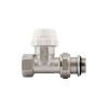
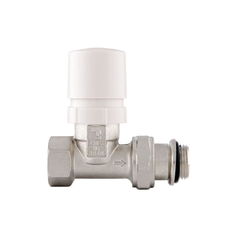
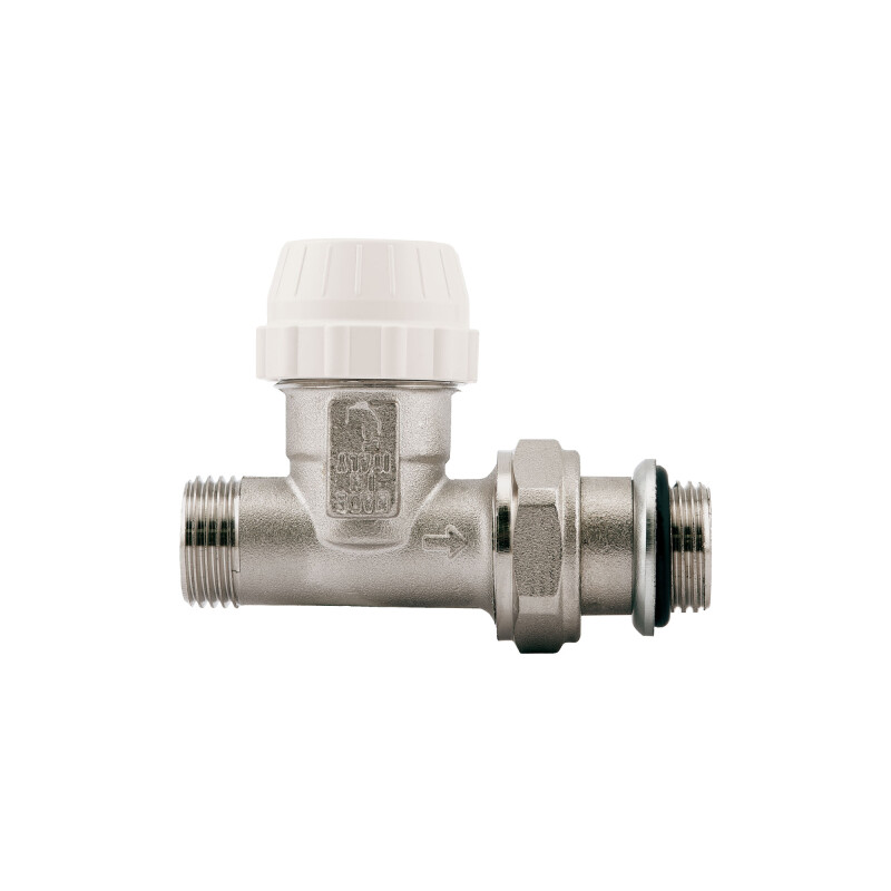
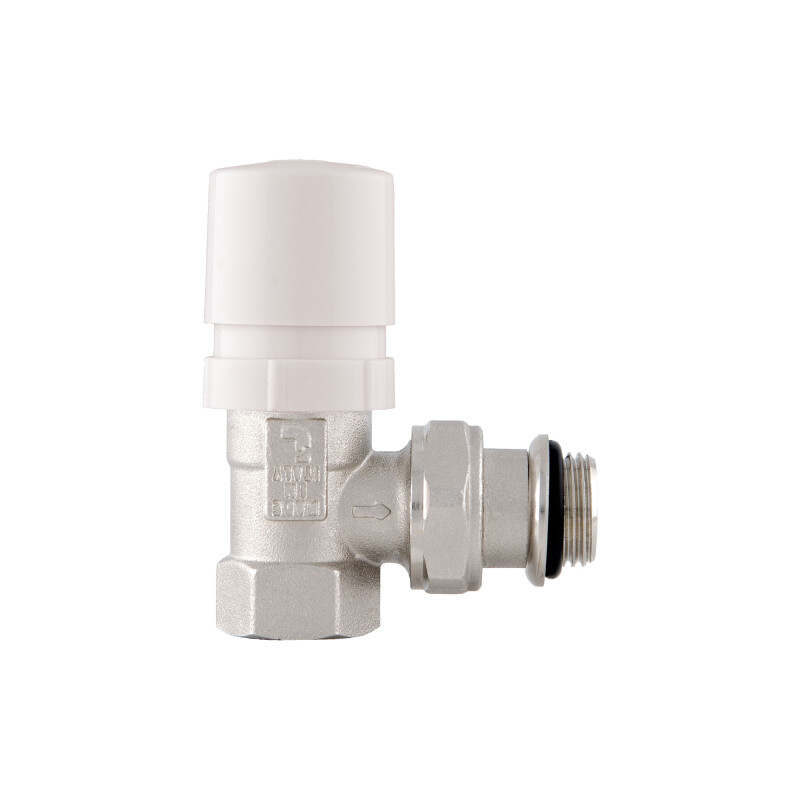
ITAP SpA thermostatic valves are used as fluid heat-carrying shut-off elements feeding into radiators. They are composed of valves furnished with a special internal bonnet that is able to permit or stop the flow of water when it is combined with a thermostatic control head. This enables setting the maximum reachable temperature in a room: once the said temperature has been reached, the thermostatic control head, by pressing the bonnet, closes the valve completely, thus isolating the radiator from the rest of the system. If the temperature next to the thermostatic control head does not represent that of the room (for example, because there is a radiator cover), it is advised to install the thermostatic control head with a remote sensor Art. 891SD.
ITAP SpA thermostatic valves are classified as low inertia since, when there is a change in temperature of the room, the response of the thermostatic control head occurs within and not beyond an interval of 40 minutes.
Should it be necessary to prevent the set temperature on the thermostatic control head from being changed, it is possible to block regulation directly from the control head.
To facilitate installation, the valve shanks and lockshields are pre-supplied with an O-ring seal.
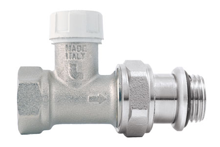
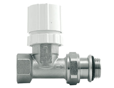 The thermostatic valve is composed of a brass body and bonnet with a pin and counter-spring in stainless steel. The thermostatic control head is a temperature proportion regulator composed of an internal sensor with an oil-filled element. Once the temperature has been set on the control head, it directly activates the iron pin, thus determining the position (closing or opening). If room temperature is below the set value, the liquid contracts and increases the opening of the valve. If room temperature is above the set value, the liquid expands and decreases the opening of the value until it closes completely (once it has reached the desired temperature).
Thanks to the internal bonnet, the lockshield's function is to give perfect balance to the system. With this component, it is possible to supply all radiators, even the most disadvantaged ones, in a perfect way. In order to carry out perfect balance of the various circuits, it is recommended to use the load flow / loss diagram found in this technical catalogue.
Work fluid: water (maximum admissible percentage of glycol: 30%)
Maximum working temperature: 110°C
Maximum working pressure: 10 bar
Maximum differential pressure: (with thermostatic control head installed): 1.5 bar
Threads ISO 228
Scale value from * to 5.
Adjustable temperature range : 6.5°C, 28°C.
Antifreeze position: 6.5°C
Device to restrict or lock temperature setting included.
Hysteresis: 0.5K.
Response time: Z: 30min.
Maximum differential pressure: 1.5 bar.
Art. 891SD length of capillary pipe 2m
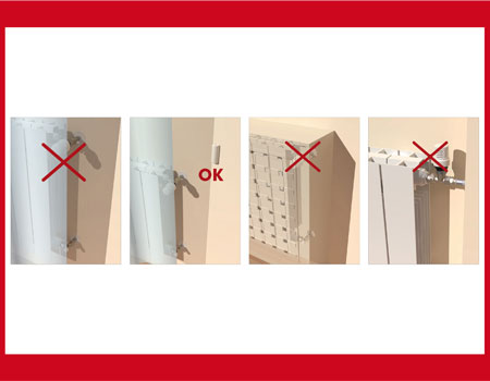
The sensitive element of the thermostatic head must not be placed in niches, or behind curtains, or exposed to direct sunlight: each of these situations may give a false reading. Should it be unable to avoid curtains or any of the aforementioned situations described, you are required to install a head with remote control (Art. 891SD).
The thermostatic heads may be protected from tampering by installing a specific tamper-proof cap Art. 891SD. See the diagram.
Refer to the numbers indicated on the control knob to set the room temperature. Each number (from * to 5) may be used for a specific room temperature.
In order to obtain better performance, the thermostatic valve must be installed in a horizontal position away from elements that may hinder correct operation (for example, away from curtains or radiator covers).
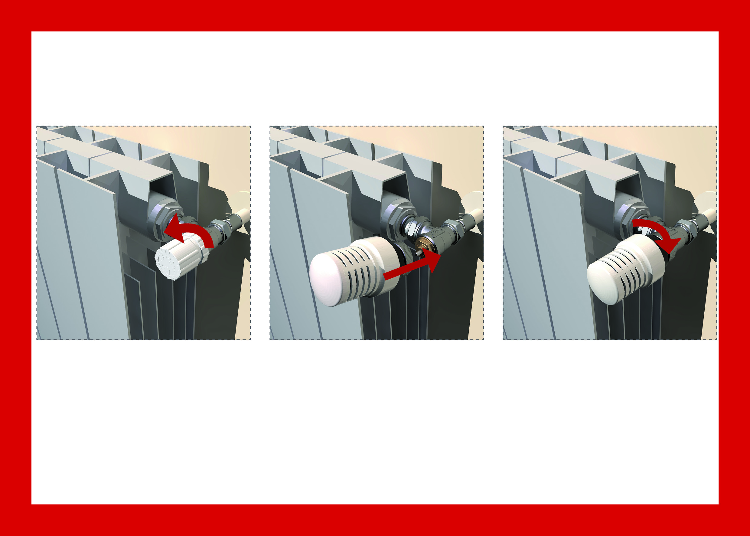
By a simple operation, the convertible valves may be coupled with thermostatic control heads: this transformation into a thermostatic valve may also be carried out with operating systems.
Remove the manual cap by unscrewing it anti-clockwise.
Rotate the thermostatic control head until it is completely open (position 5).
Move the actuator close to the valve body leaving the reference index well visible and manually screw on the nickel-plated ring until it halts.
ITAP SpA thermostatic valves are classified as low inertia since, when there is a change in temperature of the room, the response of the thermostatic control head occurs within and not beyond an interval of 40 minutes.
Should it be necessary to prevent the set temperature on the thermostatic control head from being changed, it is possible to block regulation directly from the control head.
To facilitate installation, the valve shanks and lockshields are pre-supplied with an O-ring seal.
VALVES TECHNICAL SPECIFICATIONS
The thermostatic valve is composed of a brass body and bonnet with a pin and counter-spring in stainless steel. The thermostatic control head is a temperature proportion regulator composed of an internal sensor with an oil-filled element. Once the temperature has been set on the control head, it directly activates the iron pin, thus determining the position (closing or opening). If room temperature is below the set value, the liquid contracts and increases the opening of the valve. If room temperature is above the set value, the liquid expands and decreases the opening of the value until it closes completely (once it has reached the desired temperature). LOCKSHIELDS TECHNICAL SPECIFICATIONS
Thanks to the internal bonnet, the lockshield's function is to give perfect balance to the system. With this component, it is possible to supply all radiators, even the most disadvantaged ones, in a perfect way. In order to carry out perfect balance of the various circuits, it is recommended to use the load flow / loss diagram found in this technical catalogue.
CONDITIONS OF USE OF VALVES AND LOCKSHIELDS
Work fluid: water (maximum admissible percentage of glycol: 30%)
Maximum working temperature: 110°C
Maximum working pressure: 10 bar
Maximum differential pressure: (with thermostatic control head installed): 1.5 bar
Threads ISO 228
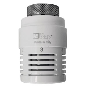
THERMOSTATIC CONTROL HEAD WITH OIL-FILLED ELEMENT
Scale value from * to 5.
Adjustable temperature range : 6.5°C, 28°C.
Antifreeze position: 6.5°C
Device to restrict or lock temperature setting included.
Hysteresis: 0.5K.
Response time: Z: 30min.
Maximum differential pressure: 1.5 bar.
Art. 891SD length of capillary pipe 2m
CONDITIONS OF USE OF THERMOSTATIC CONTROL HEAD
The sensitive element of the thermostatic head must not be placed in niches, or behind curtains, or exposed to direct sunlight: each of these situations may give a false reading. Should it be unable to avoid curtains or any of the aforementioned situations described, you are required to install a head with remote control (Art. 891SD).
The thermostatic heads may be protected from tampering by installing a specific tamper-proof cap Art. 891SD. See the diagram.
Refer to the numbers indicated on the control knob to set the room temperature. Each number (from * to 5) may be used for a specific room temperature.
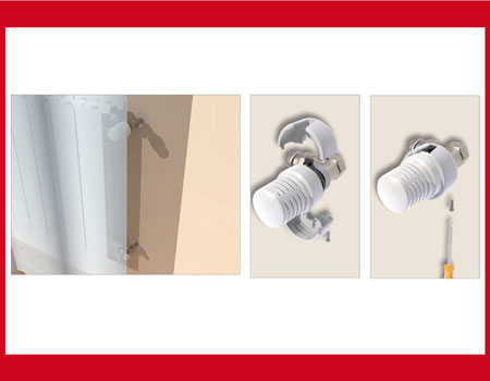
INSTALLATION
In order to obtain better performance, the thermostatic valve must be installed in a horizontal position away from elements that may hinder correct operation (for example, away from curtains or radiator covers).
By a simple operation, the convertible valves may be coupled with thermostatic control heads: this transformation into a thermostatic valve may also be carried out with operating systems.
Remove the manual cap by unscrewing it anti-clockwise.
Rotate the thermostatic control head until it is completely open (position 5).
Move the actuator close to the valve body leaving the reference index well visible and manually screw on the nickel-plated ring until it halts.
Technical features
Applications

Request information for:
Thermostatic valves for radiators